.png)
370 results found with an empty search
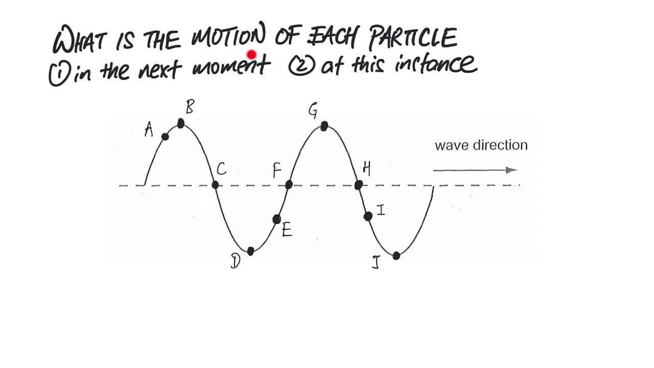
- Determine the motion of the particles on transverse wave
Instead of imaging how the particles will move and guess their motion, there is a technique which can help you to determine that. In addition, when particles are in phase, it means that both particles on the wave have the same velocity and same displacement. It means both have the same speed in the same direction and same distance and direction away from the rest position. Particles that are out of phase means both are having the same speed but in opposite direction. Refer to the video below to find out more. Question 01: 2005/2008 PP P1 Q20/Q18 Question 02: 2018 PP P1 Q24
- Identifying what lens, focal length and image from 2 rays – PP2010P1Q23 and SP2014P1Q11
These 2 questions are actually the same. Q23 is from 2010 Pure Physics P1 while Q11 is from 2014 Sci Physics P1. Take a look at these 2 questions. If you are not sure, view the video below for the explanation. Answer to Q23: Option A Answer to Q11: Option D If you do not know how to answer these 2 questions, view this video and also refer to the lens summary below.
- 2016PPP1Q40 – Voltage and Power of Bulb Y when X is switched off - 2013PPP1Q40 heaters
2016PPP1Q40 Solutions: Option C [There is another similar question in 2013 Nov Pure Physics P1Q40. The answer is Option C too. Refer to the last section of this post] Refer to the 2 videos below. The 1st one is faster if you know that the bigger the resistance, by proportion, the bigger the potential difference of the component as it will take a larger portion of the emf wrt to the other components in series. This method is especially useful for MCQ. If you are still unsure, you may put in values to find the I, V and P across the components. This will be more tedious and time-consuming. Another similar question is 2013 Nov Pure Physics P1 Q40.
- Video 01 How to find resultant force of two or three forces (without drawing vector diagram)
Below are some examples of questions that involve finding the resultant force due to two or three forces. Below are the questions in the video. Any question you are unsure, you can just watch the respective section of the video based on the time stated. (1) 2010PPp1q2 similar to 2002PPp1q7 (0s to 3.02 min) Ans: Option D and D respectively (2) 2013SPp1q2 (3.02min to 4.25 min) Ans: Option A (3) 2005PPp1q10, 2012SPp1q1, 2018PPp1q2 (4.25 min to 6.40 min) Ans: Option A (3) 2014PPp1q8 (6.40 min to 7.48 min) Ans: Option B (4) 2019PPp1q2 (7.48 min to 8.22 min) Ans: Option B ( 5) 2020PPq1q3 (8.22 min to end) Ans: Option B
- Video 02 Finding resultant force from vector diagram provided
(1) 2003PPq1q7 (0 min to 2.42 min) Ans: Option A (2) 2023PPp1q4 (2.47 min 3.54 min) Ans: Option C (3) 2018PPp1q2 (3.45 min to 6.22 min) Ans: Option D (4) 2011PPp1q6, 2016PPp1q6 (6.22 min) Ans: Option A
- 2010SPP2Q12 Fuel gauge using variable resistor
Solutions: As the fuel level drops, the float which stays on the fuel surface will descend. The rod which is attached to the float will turn clockwise about the pivot X. As the rod turns, the resistance on the variable resistor increases. This increases the resistance of the circuit. Hence the current flowing through the circuit will decreases, causing the needle to deflect more to the left, indicating towards E (empty). Thus the reading on the fuel gauge decreases. Solutions: (i) Both the fixed resistor and sensor are in series. Total effective resistance Re = 5000 + 1000 = 6000 ohms V = IR 12 = I x 6000 I = 0.0020 A Hence potential across Y, V = IR (where I is constant in a series circuit) = 0.0020 x 1000 = 2.0 V (ii) When the temperature increases and the resistance of sensor Y decreases, the total effective resistance of the circuit decreases . Current flowing through the circuit increases. Since V = IR, where the R of the fixed resistor is a constant 5000 ohms, as current I increases, the potential difference across the 5000 ohms resistor will increase.
- Ticker Tape Timer
Ticker tape timer is a device which punches dots on a tape at specific time interval. The tape can be attached to a moving object. With information of the frequency of the ticker timer and the spacing of the dots, we are able to analyse the motion of the moving object. View the following videos to understand more about the ticker tape timer and also some typical questions on ticker tape timer. Explanation of Ticker Tape Timer Questions on ticker tape timer
- Why the fuse and switch must be on the live wire?
A common mistake is to state that the reason for switch to be on the live wire is “so that the switch can turn on/off the appliance”. This explanation is wrong. In general, in the event where the fuse is blown or the switch is open, it disconnect the appliance from the high potential of the live wire. So the appliance will no become ‘live’ and it is save to touch even though there is a fault. Refer to the video for the reason why switch and fuse must be on the live wire. Refer to the notes given
- Basic Concepts on DC Circuit – River System
The ‘D.C.’ here mean direct current . It means that the current flows in one direction in the circuit . The direction of the direct current refers to the conventional current , and it flows out of the positive (+) terminal of the cell / battery, around the circuit and flows back into the negative (-) terminal . [Note: the direction of the electron flow is opposite to the conventional current] To understand DC circuit, it will be useful to relate to a river system. Refer to the 3 videos below to learn more about 01: DC circuit similar to river system, 02: Series Circuit 03: Parallel Circuit and 04: Combined Circuit. 01: How is DC circuit related to a river system 02: Series Circuit 03: Parallel Circuit 04: Combined Circuit (Series and Parallel) Now, after you have the basic concepts and rules for the circuits, let’s look at some simple example to reinforce you understanding. Example 01: Series Circuit Example 02: Parallel Circuit Example 03: Combined Circuit Example 04: PP2012P2Q7 DC circuit : pd across 2 points on two separate branches.